
the technical features:
Technology - processor-controlled heated grip control with visual feedback
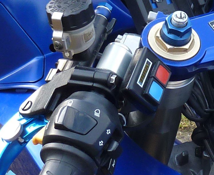
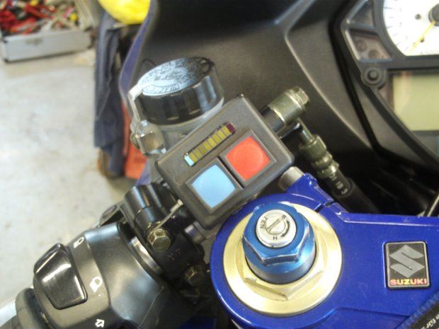
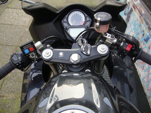
Version - waterproof control panel for the handlebars and splash-proof control panel for the interior of the motorcycle
Operation - two large colored buttons
Signaling - yellow LED bar with red and blue end LED
Display - signaling of over- and under-voltage voltage, signaling of the heating level, automatic darkening of the display after time
Self-protection - checking your own function and signaling errors
Protective mechanisms - Short-circuit proof on the heated grip connections, no internal safety elements necessary
Program - heating phase (100% heating output) with automatic switchover to normal operation (0% - 60% heating output), on-board voltage control
the project
Spring 2009
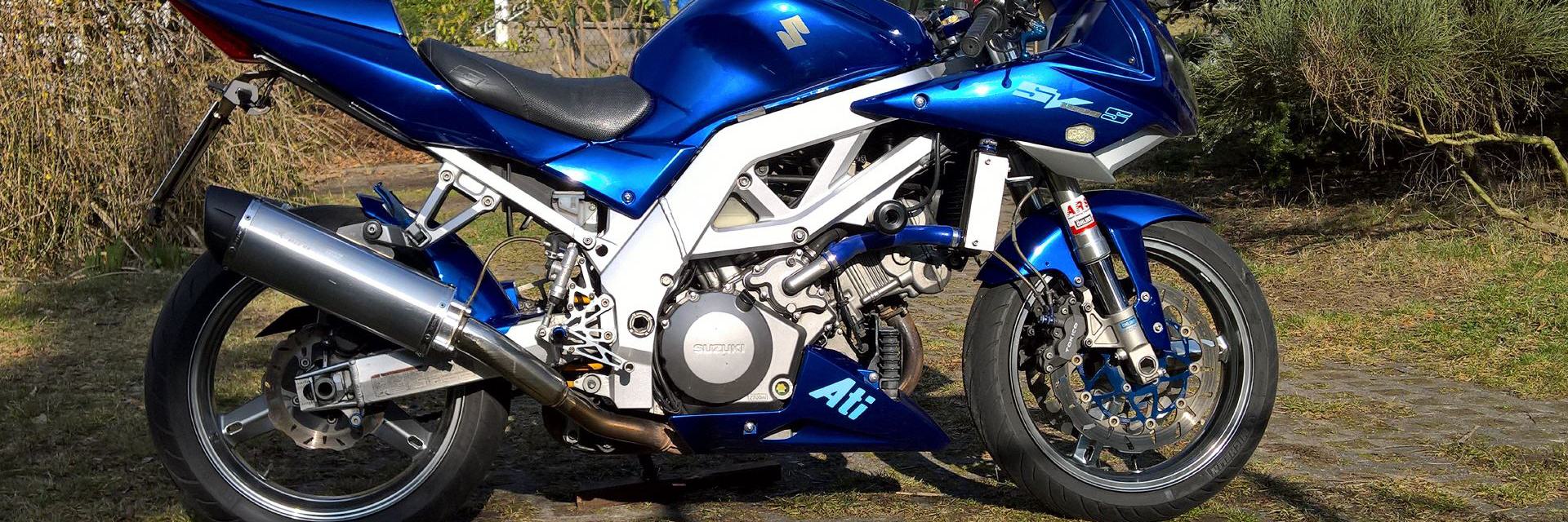
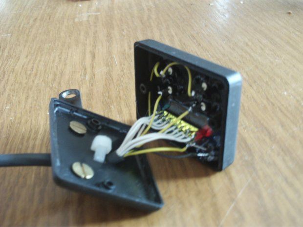
So I decided to divide the control into two parts. For ergonomics, I chose two fairly large waterproof push buttons, which are warmer/colder in the colors red and blue depending on their function. The smallest possible case available with a tightness option resulted from the depth and size of the buttons. Since the display should be designed in such a way that even a non-technician can operate it without any problems, I installed an LED bar to display the status. The bar is limited on the left and right by an LED depending on the function. A blue LED at the cold end and a red LED at the warm end. In between, yellow LEDs are responsible for displaying the respective position.
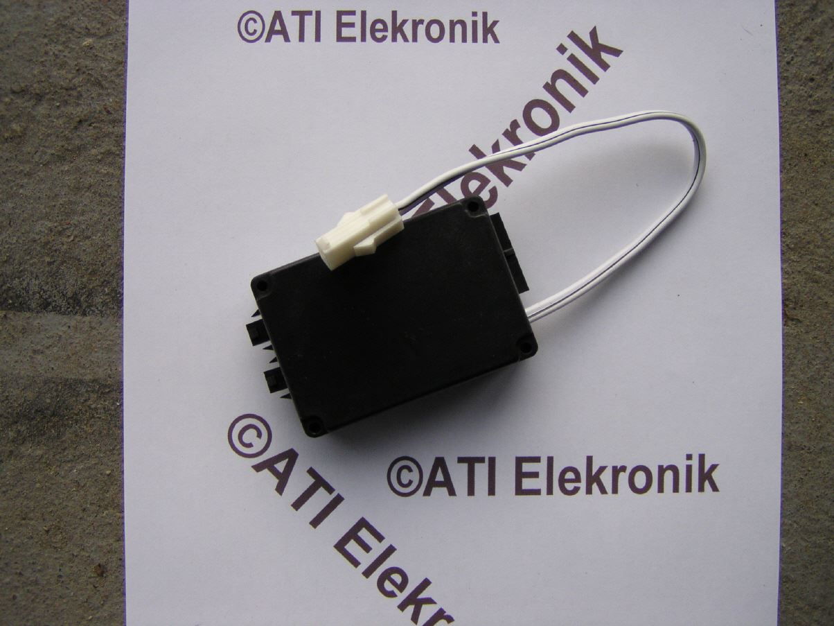
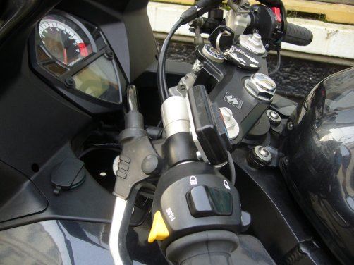
The actual control is in a second box directly below the speedometer. Since the cable length is not a problem, you can of course choose any other location to accommodate the box. If necessary, however, the supply lines for the heated grips must be extended, which are usually not very long on the part of the manufacturer.
All connectors are designed with latches. This prevents the contacts from loosening involuntarily, even in the event of strong vibrations.
A single-chip processor from the Open Micro family works inside. The Open-Micro is a 68HC908Q* controller from Freescale (formerly Motorola) with flash memory.
a few details
|
|
|
|
|
|
Since the processor is not necessarily used to its full capacity just by controlling the heated grips, I have integrated a few additional functions.
Additional functions (something is always flashing here)
The heated grips can only be operated if the on-board voltage meets a minimum value. If the battery is discharged, the heated grips cannot be switched on. Since the display is dark during normal operation, the heated grips cannot accidentally discharge the battery. This protection also applies when the engine is running. If the alternator ever gives up and you are still a few kilometers away from the safe haven, as few consumers as possible should be switched on. The heated grips are a power guzzler that should not be underestimated. Undervoltage is indicated by four yellow LEDs flashing and moving towards blue next to the blue limit LED.
If the alternator regulator breaks down, the voltage in the on-board electrical system can exceed the permissible voltage. In the long run, this would have serious consequences for the on-board electrics/electronics. This condition is indicated by rapid flashing signals with a running effect in the red direction of the top four LEDs (near the red limit LED).
Normal operation (nothing flashes here)
When you start the heating (pressing one of the two buttons), preheating starts. Here, just like with the step switch supplied with the heated grips, full voltage is applied to the heated grips. The processor ensures that the device automatically switches down to a low level after 1.5 minutes of heating up. During the preheating period, the LEDs on the display as visual information for preheating run from blue to red to signal as a treadmill. The border LEDs (red and blue) are always visible, which makes orientation easier even in the dark. Once preheating is complete, the system switches to normal operating mode. The limit LEDs light up and the current status is displayed. After four seconds all LEDs go out. Each press of one of the buttons turns the LEDs back on and increases or decreases the temperature of the handles. A total of 15 levels are built in, ranging from zero to 60% heating output. After 4 seconds of not pressing the buttons, the display LEDs are switched off again.
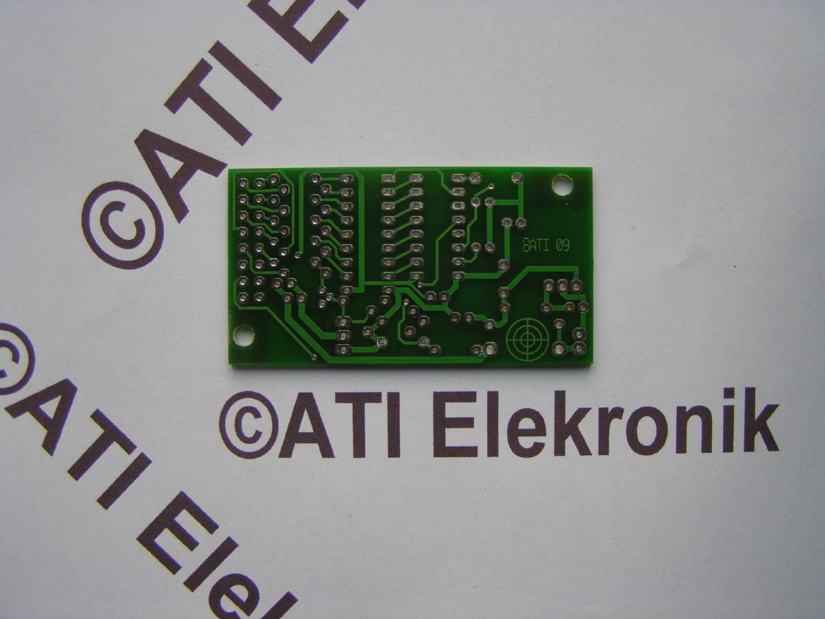
Technical implementation
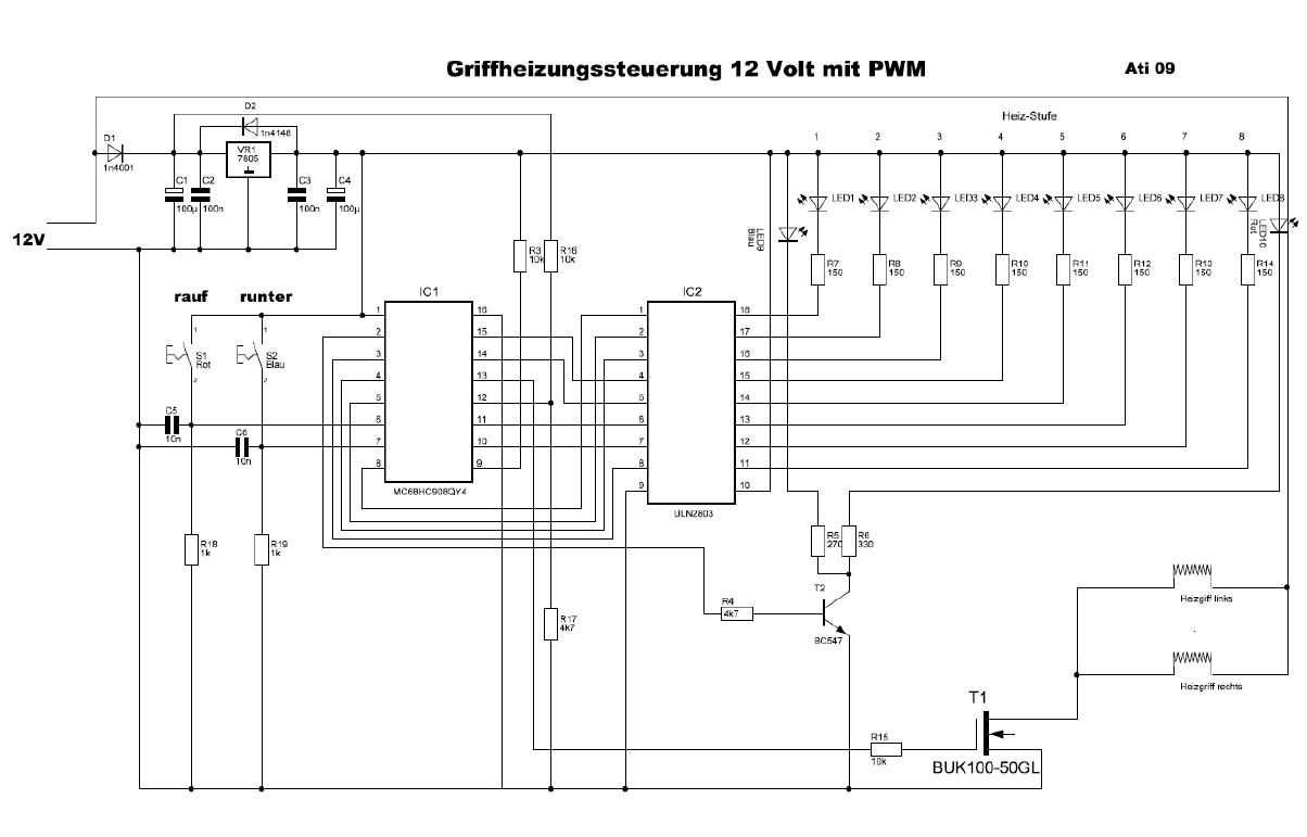
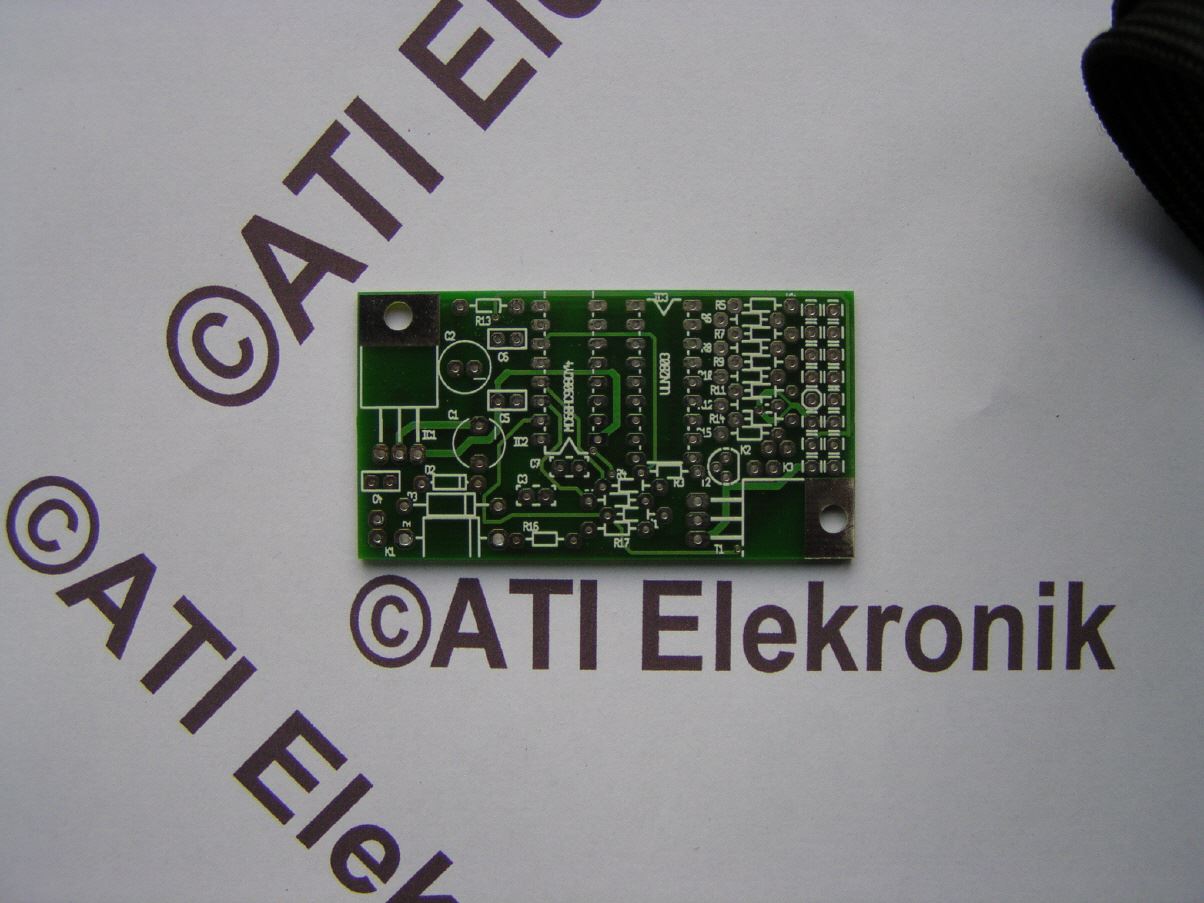
The control is carried out by an Open Mini (68HC908QY4). It has 14 ports. Four of them are defined as inputs. The remaining ports are outputs. The inputs query button operation, board voltage and possible programming (status switching). The hardware is unspectacular, as the processor handles key debounce and voltage conversion and the rest is purely digital.
On the output side, 8 ports are defined for the status LEDs, one port for the limit LEDs and one port for the pulse width modulator (PWM) for the heated grips. Since the aim was to protect the processor ports against possible short circuits, for example due to damage to the cable to the LEDs, a line driver IC was used there. This IC can also process the power dissipation of all connected and switched on LEDs at the same time, which would overwhelm the processor. The series resistors limit the LED current. The two limit LEDs are switched together using the transistor T2.
Click on the images to see them in their original size
|
|
|
|
|
|
Due to the high current flowing, a little more effort is required to control the heated grips. The use of a power MOS FET is recommended here. However, the switching speeds must be optimized for these currents, otherwise the MOS-FET will become too warm despite the digital circuit. The following consideration:
With a constant current of 5 amps, there is a power loss of around 0.6 watts, so no cooling is necessary. However, full operating voltage is only available when switching on. In between, the PWM switches permanently. However, the switching behavior of the MOS-FETs is more problematic. Here, high currents and voltages occur simultaneously along the drain-source path of the MOS-FET. This leads to losses and thus to heating of the MOS-FET. These switching losses are greater than the losses in the conducting state. Therefore, switching must occur as quickly as possible. The gate, which behaves like a capacitor (internal resistance extremely high), must be charged or discharged as quickly as possible when switching. This time is determined by the capacitance of the gate and the internal resistance of the control stage. So in order to switch large currents with large MOS-FETs (have larger gate capacitances), quite large switching currents are also required. The internal resistance of the control stage must be as small as possible. But the processor does not have such an output stage. An additional control stage would therefore be necessary. In addition, the low internal resistance of the drain-source path of MOS-FETs, which is its advantage, is only achieved with a control voltage at the gate of approx. 12 volts. However, the logical voltage at the processor output is only a maximum of 5 volts at high level.
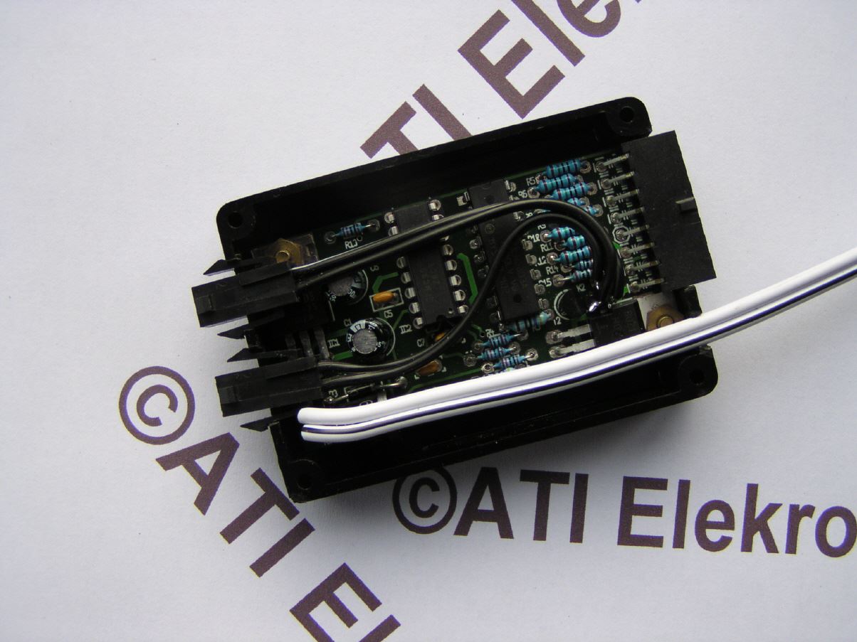
Since adding a control stage would increase the overall size of the electronics again, I used a logic level TOP-FET. This already contains logic for control. The Drain-Source ON resistance that can be achieved is 0.125 ohms. The big advantage of this MOS-FET is the integrated control stage, which also ensures level adjustment to the logic level of the processor. The integrated short-circuit monitoring is particularly advantageous, as it prevents the MOS-FET from being destroyed in the event of a short circuit.
The PWM is not clocked very high, but still high enough that there are no noticeable repercussions from constantly switching the handles on and off in the on-board electrical system. Nevertheless, the switching currents cannot be neglected. Contrary to my original ideas of using a simple power MOS-FET with a very low drain-source resistance of 0.04 ohms, the TOP-FET, despite optimized control, needs a small heat sink (it generates approx. 3 watts of power loss), which is in the housing remains. With the cooling plate it only gets lukewarm, which is completely sufficient.
Click on the images to see them in their original size
|
|
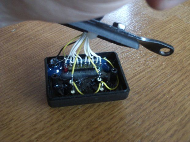
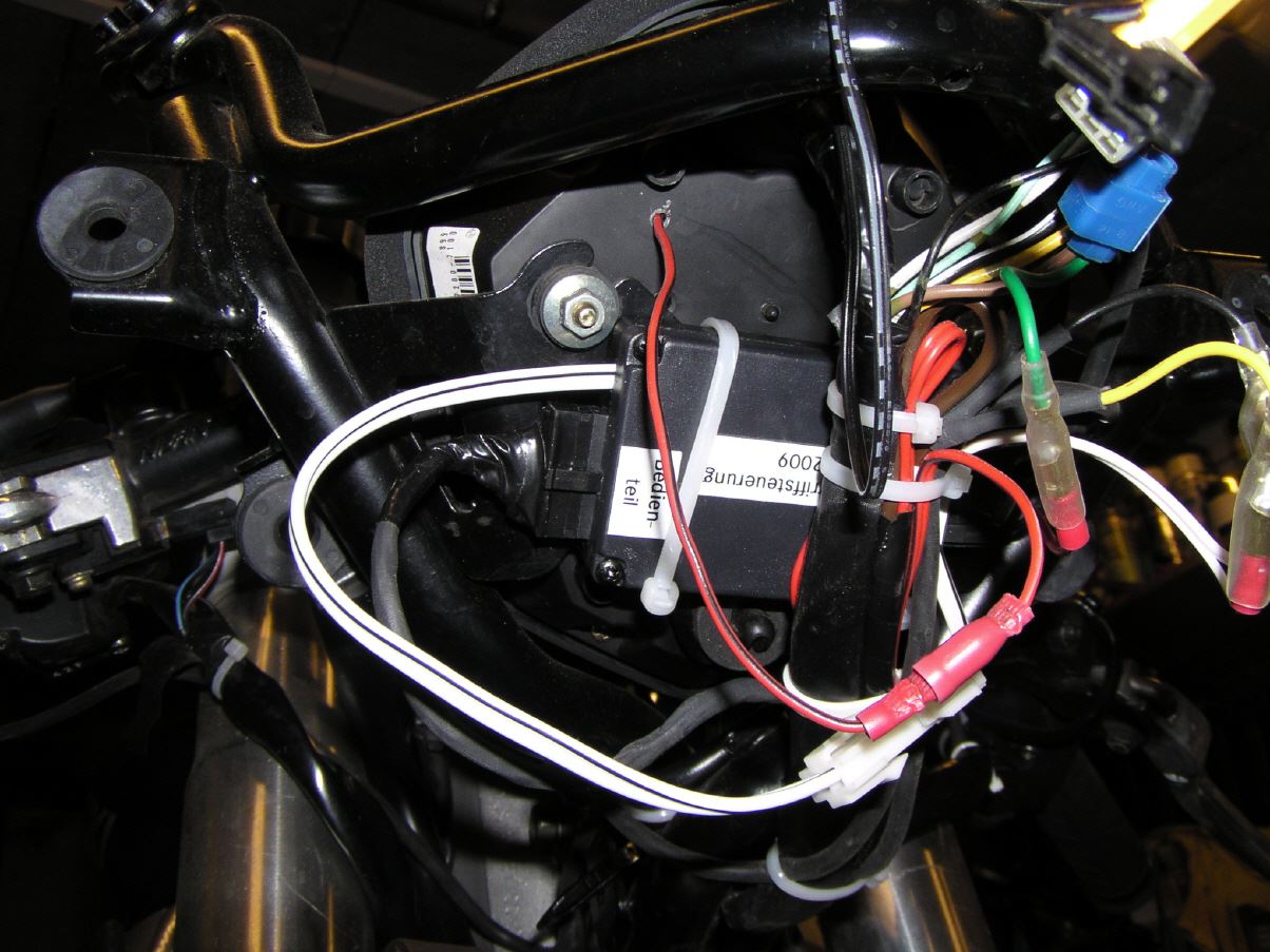
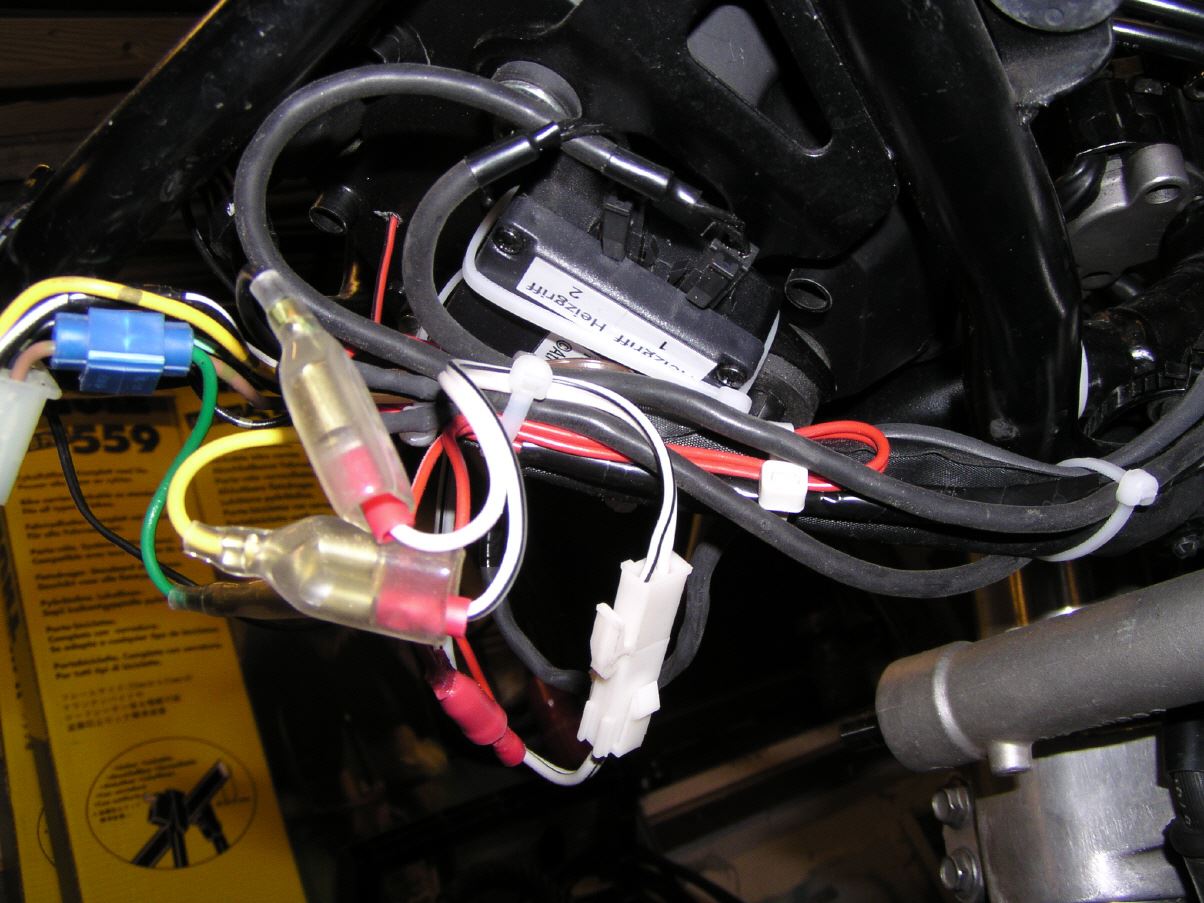
This housing can be mounted on both the left and right using a screw-on bracket. In the example it is a small piece of flat steel. But that could also be a clamp. |
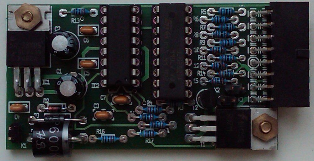
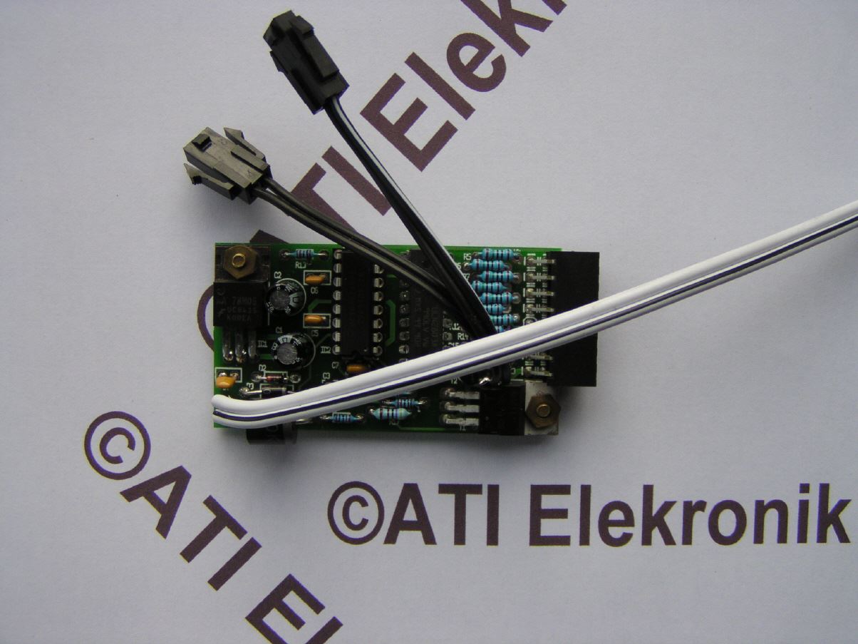
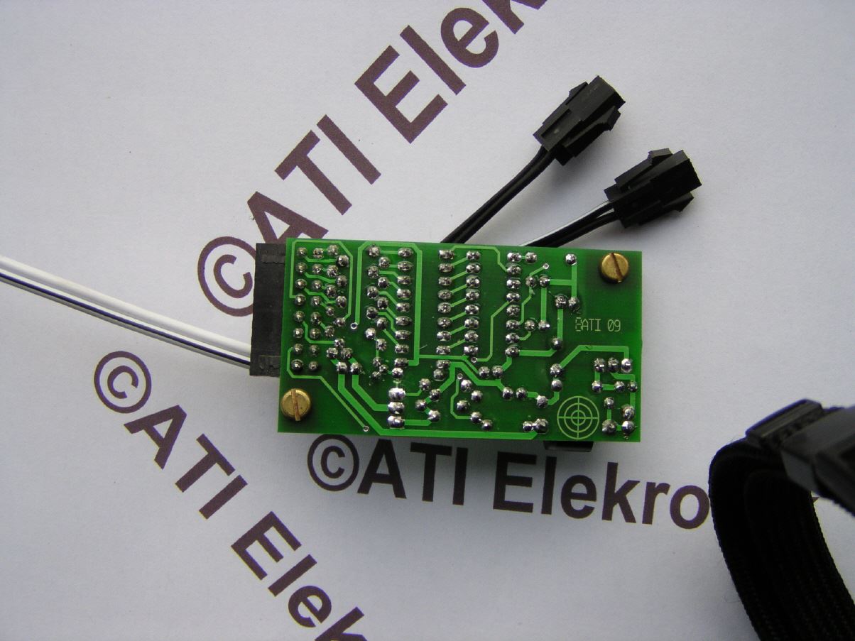
The board's structure includes a two-row 16-pin connector from the N-Lock Micro family, via which the control panel is connected. The connectors for the heated grips are now designed as a whip connection with Japanese plugs. This means that the original plugs can be used on the Daytona heated grips, for example. The operating voltage is supplied via a cable with an N-Lock mini connector. This means that the module can be completely removed or changed in a very short time or when motorcycle parts such as the pulpit or similar are removed. The plugs are unmistakable. This prevents accidental polarity reversal.
To connect the heated grips and control them, you should install an extra cable from the battery including a line fuse and switching relay. This line can then also supply an on-board socket or similar. And here I come back to the mentioned second line from the SV speedometer. The cable from the gear sensor is already routed into the speedometer. If you pull in a second cable at the same time, you can route the "ignition on" signal present in the speedometer back out (back under the seat) and thus switch the load relay for the additional consumers. This leaves the original wiring harness alone and is a safe solution. Of course, this can also be solved differently, for example by using a parking light on the wiring harness or the ignition for relay control.
Addendums (October 2009)
What is new is that the voltage is still monitored when the heated grips are still switched off. I hadn't taken this into account when programming at first. The voltage monitoring only became active after the control was switched on.
Also new is the option to cancel the heating phase and switch to normal operation. This makes sense, for example, if you only need to switch off the engine briefly and then want to continue driving again. Then the handles are far from cold and a normally long heating phase would be quite uncomfortably warm.
And because I was already there, I also made a real elimination possible. If you set the control to the lowest position (only the last yellow LED is on), the pulse width modulator is already at 0.01%. It's not 100% zero but 99.99%. If you press the down button further down again, the control is switched off completely. To do this, all LEDs are switched off immediately and there is silence. However, the voltage monitoring is still active.
What's the point of all this? This means you can preheat the heated grips again if it suddenly gets too cold and, above all, no more electricity is consumed when the PWM is switched off. At 0.01% something still flows, even if very little.
The test in the Dolomites was successfully completed. I added a small attenuation to the voltage monitoring. This means that a multiple overvoltage or undervoltage event must first occur for the warning to become active (but we are still talking about milliseconds). With an outside temperature of around 5 degrees, heating level 6 was sufficient. Due to the constantly varying temperatures during the test drive, the relatively fine gradation was able to come into its own. It was very pleasant, so to speak.
exemples
|
|
|
| |