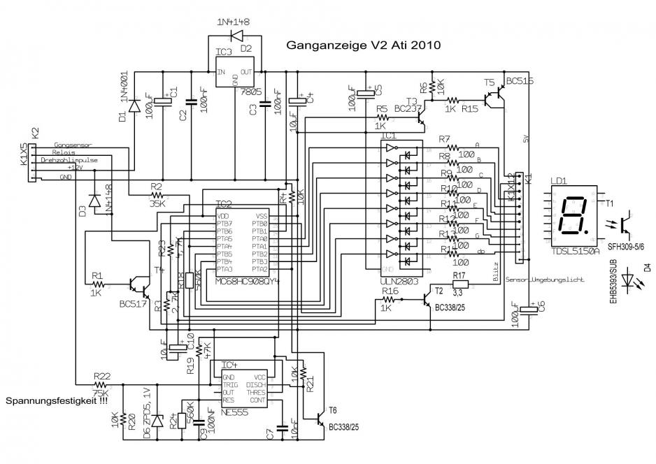
Gear indicator V2
V2 of the gear indicator
By 2009 a joyous motorcycle year has been completed . The function of the gear indicator V1 is great and aroused among some contemporaries need. And also I 've been thinking again about little further developments. So I had the realization that it would be useful to provide the gear indicator with a mapping. Thus, the deviation of the effective sensor voltages caused by the ECU , be balanced and it no longer comes to the occasional display of jumping in 6th gear or 6th gear to display at idle with the engine .
And because so further inquiries need to display there , I have now developed also a decoding without the great decoder D348 . Attention was the still existing brightness control of the display. Then it came to me in the first place. I now put a ambient brightness controlled pulse width modulation of the brightness .
And because it is so beautiful and the ideas do not subside . There is now also a lighting control system for the headlights and a shift light . The light control switches on the headlights of the SV1000 and off. The SVs are known to have no light switches. Ignition on means of light. This is not just an advantage, but at least you will not forget to turn on the light.
A further disadvantage is that the entire headlight current flows through the ignition switch and the plug contacts , which have a number of SV drivers a charred connector (green connector ) and a fairly loose hope of breaking down the road has introduced .
With the gear indicator V2 , it is now generally possible to change this. It controls a load relay the headlights . And it does so that the headlights are turned on only when the engine is running. If the engine extinguished the headlights. The " luxury " automatic light on and off I did not want to give up. The side lights are not affected by this change. Ignition on is now called to stand light.
and anyway when the rotational speed of the engine is evaluated , it can also be housed a shift light . The shift light is programmed according to vehicle passage for different speeds. In lower gears he flashed earlier because the engine revs up much faster than in higher gears . And because the brightness of the gear indicator is already regulated anyway , of course, the brightness of the flash circuit is also throttled down in the dark .
The functional model has already completed several test without problems. Now follows the prototype .
To make it even once to say. It makes no difference whether 650s or 1000s ( edge ) Only in the transition mapping they differ. Shift light and lighting control are optional usable components. They are available and can be used as needed - but do not .
To use the light control requires a revision of the wiring harness of the SV . Suzuki has provided the orange wire with a y- distribution in the connector between the head pipe and the air filter box. At this point, the orange wire strands must be separated which goes to the connector for the light switch. The severed wire is extended and pulled back under the seat . Here one can build a load relay that turn on the headlights ( that would be the orange wire).
I have installed an overload relay with integrated flat fuse for this. This saves a loose rumflatternde backup.
|
|
|
Anything you do on the bench is , without any external influence . There, it works so as expected. But in practice it as something different. There are relationships and dependencies . The prototype was still quite a few weaknesses. On one hand, vary the junction voltages in real operation but a little more than expected. On the other hand, the firing pulses are irregular / inaccurate filter out through the capacitive decoupling used first . The tap of the high voltage is also not absolutely necessary and a trickige solution to improve the signals using a non- retriggerable monostable I would not go. So I take now only times the ignition signal directly on the primary side of the ignition circuit from . The problems caused by the ignition coil damped oscillations demolition must of course be eliminated. I 've tried using a test circuit directly to the motorcycle. The input pulses are now digitally usable.
Originally I wanted to build a completely in the speedometer existing solution . But this is not feasible , since the speed signal is not present there in its pure form . The signal goes through the ECM to the speedo .
After a few more hours to refine the functions the result is now initially satisfactory. The current focus problem is still highly fluctuating transient voltages . I have the time to test with another ECM , or an additional comparison with other SVs yet . If the fluctuations are there also so strong, it is not surprising that the SV has no standard gear indicator ;-)
So it flashed occasionally times when driving in 6th gear at 5500 U / min. The reason that I have programmed to show purposes at idle the shift light . At 5500 U / min If you drive in 6th gear now over 5500 rev / min and the gear display switches briefly to 0 from idle , then it flashes stop . This show function has been so immediately taken out .
In the meantime, I can also find the appropriate connector for the gear sensor . The vexing Soldery on the gear sensor connector is thus "final consumer" over. To gear indicator , there is a plug and play adapter to do so.
Well , always step by step.
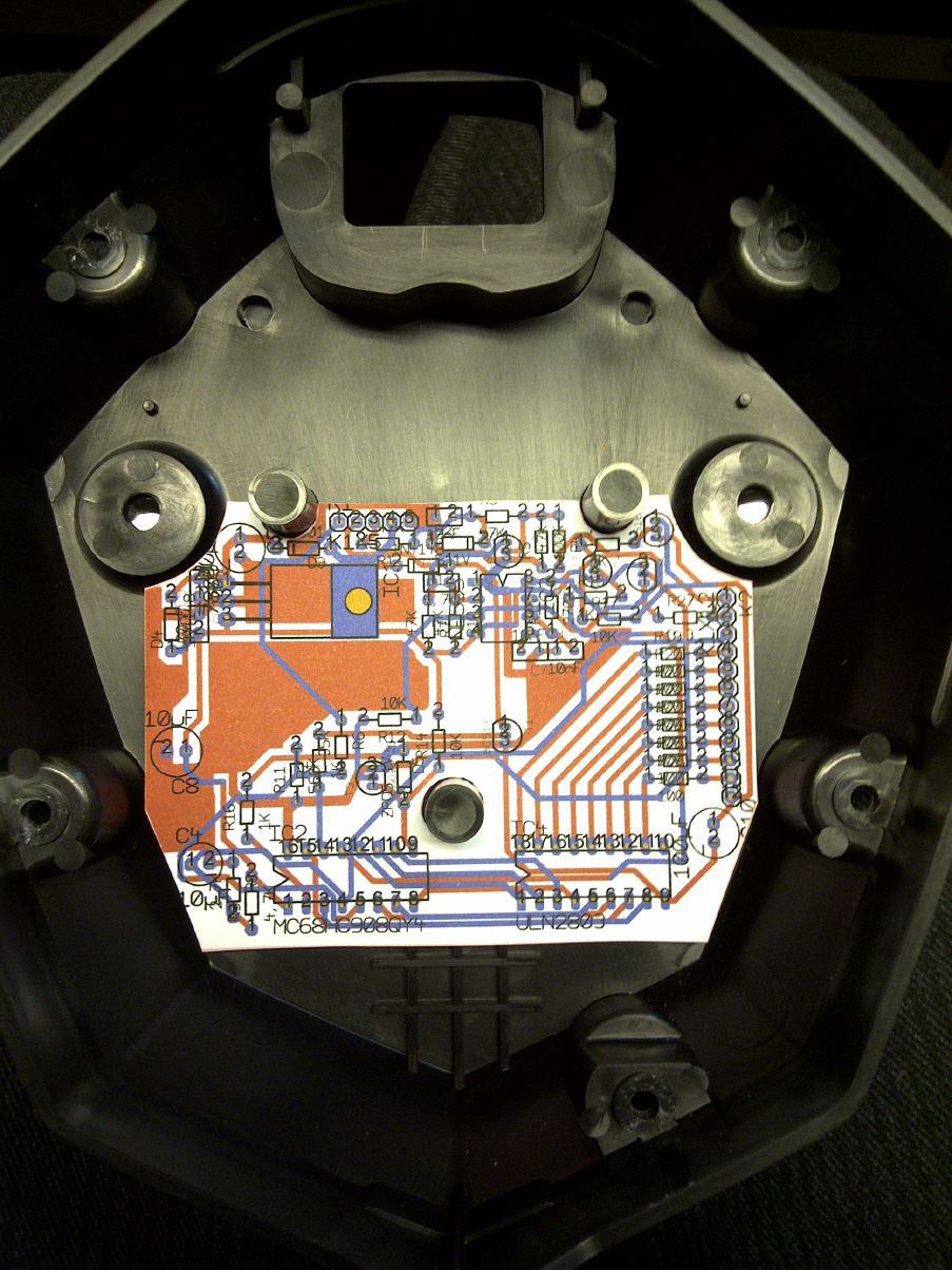
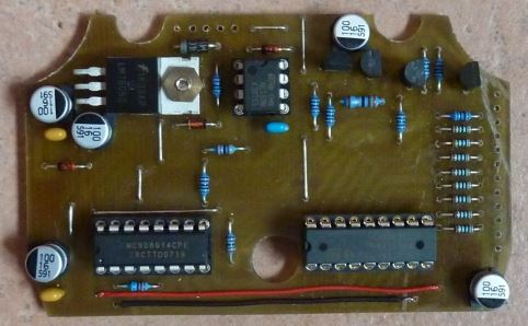
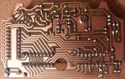
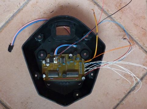
Einbaumuster der neuen Platine der Ganganzeige V2
The latest thinking are provided with first results. It is matured for a new pulse treatment of the firing pulses . I am now but the slightly more complex and trickigen way of a non- retriggerable monostable multivibrator gone . Why ? The firing pulses from the ECU are easy to dirty than that obtained unique over the entire speed range speed pulses .
How does it work?
At the time of firing of the input transistor of the Zündimpulsaufbereitung is controlled by the high ignition voltage . By a switching edge in turn is the timer , which is connected as a monostable multivibrator , triggered. The holding time of the monoflop then the base voltage of the input transistor will be set to HIGH . This can further impetus not pass through the transistor. He's already turned on. After the holding period of the monostable multivibrator flips back to its original position and thus deprives the input transistor to the base of the operating voltage so that it locks and is again available for re- triggers.
The holding time of one-shot must be at least so long that no longer cause the unwanted vibrations of the ignition to trigger . The output of the monoflop , now present at the exact speed pulses , which in turn triggers the frequency counter of the processor , so that the switching points of the switch initiates the flash, and the headlights.
Initial tests on the motorcycle using oscilloscope showed a flawless function without any interference . So now comes first again a prototype.