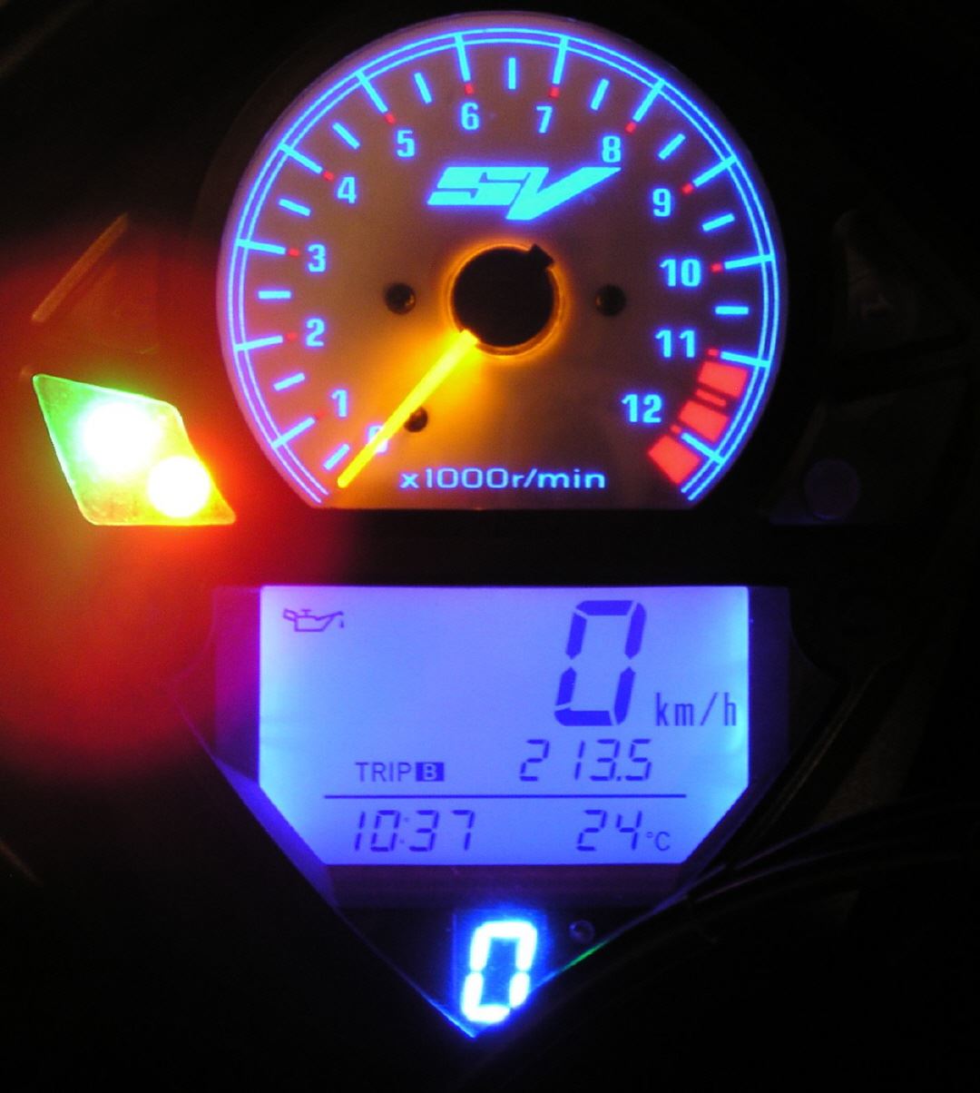
Final version of the gear indicator V3
The gear indicator V3 includes several features that go beyond just gear indicator by far. With it, a shift light is operated in addition to the pure display of the selected gear for sporting purposes , which was fixed for each course individually to a certain speed . In addition, the V3 can control the headlights . This reflects the lack of light switches. When starting the engine the headlights are off and only be connected when the engine is running .
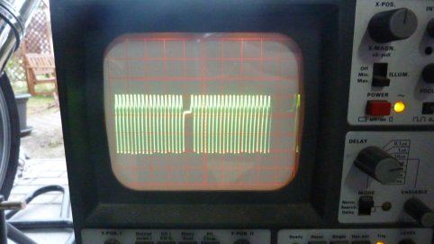
For the generation of the required speed signals from the crankshaft position sensor is tapped . This is a small coil which has housed the generator , and generates the rotation -angle-dependent with the rotation of the motor voltage pulses. These voltage pulses are evaluated in the ECU in conjunction with other of the SV sensor values and calculate the required fuel injection quantity for the engine operation .
This sensor generates voltage pulses in the range of 5 volts at a fairly low extractable power . After all, enough power to drive subsequent electronics.
Who is a circuit diagram of the SV K3 up his own calls (color or black / white does not matter) will probably look in vain for the crankshaft sensor. You forgot to label it.
It is located in the drawing directly to the indicated alternator (generator) and should also bear the name CKPS (crankshaft position sensor).
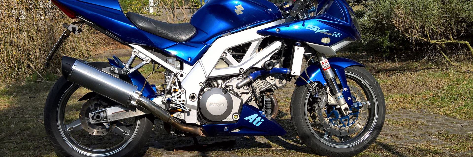
Coming from Lima go two wires to the connector to the left of the battery to the frame (see photo). The incoming lines are green and blue. The wider lines to the ECM but are then green and green / blue. Green / blue goes to N + of the ECM (pin 26) and green goes to N-ECM (pin 30).
These two lines must be tapped.
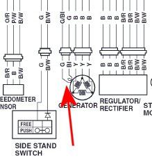
 Oszillogramm Kurbelwellenpositionssensor
So Looks not bad. Voltages are easy to handle. Likewise, the frequencies.
There are 22 pulses per revolution, which abut against the crankshaft position sensor. I naturally wondered why the oscilloscope window makes a synchronization jump. after consideration of the rotor of Lima is now clear. The 22 pin for the sensor are distributed asymmetrically. There are 21 sysmmetrische gaps, which are then completed by a larger gap. This is for my use case, but unimportant, because I simply count the pulse edges and not when they occur.
So This is the pulse treatment in the bag. Then the pulse numbers are evaluated by a frequency counter in the processor.
Änderung am Gangsensor
|
|
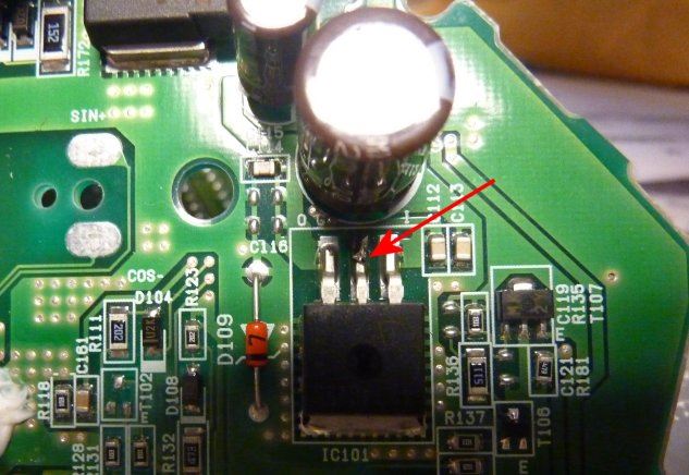
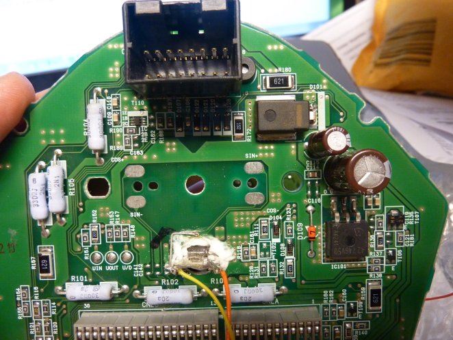
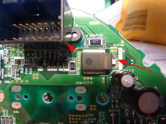
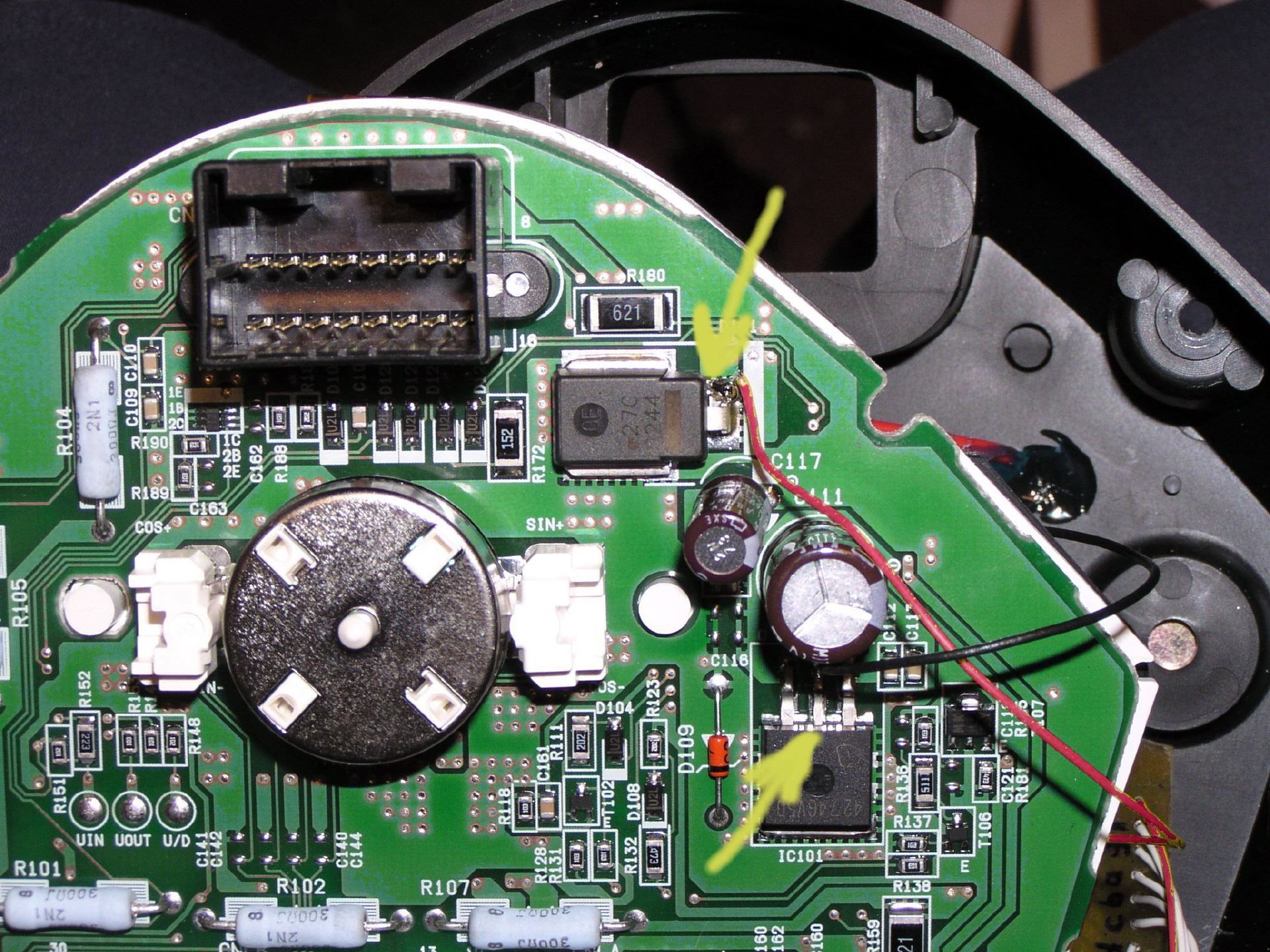
In the pictures you can see how the change looks like. Pink sensor cable to the ECU is controlled by the switching transistor 0815. In the collector line is the "Gear" resistance. If the transistor is so driven, which is the case in the "non-idle", then the default by solid resistance transition to the ECU is sent. In neutral position, the base is pulled to ground and the transistor blocks. Then, the ECU line is pulled to 5.3 volts as the original function. When driving the transistor the base current flowing is so low that the LED on the speedometer remains dark. The internal resistance of the side stand relay produces a lower forward voltage than the neutral LED on the speedometer. It thus remains dark
Gangsensoradapter V3
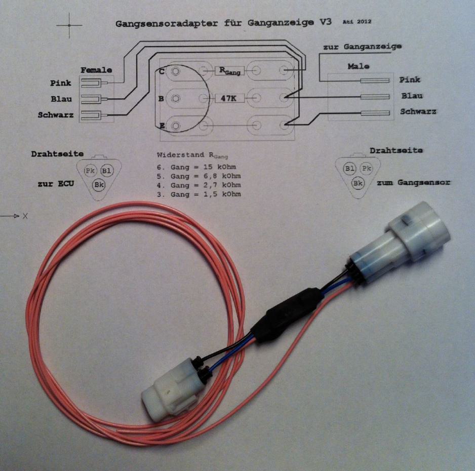
Gangsensoradapter
Gear indicator adapter ready
Subsequent to the new pulse shaper for the GA V3
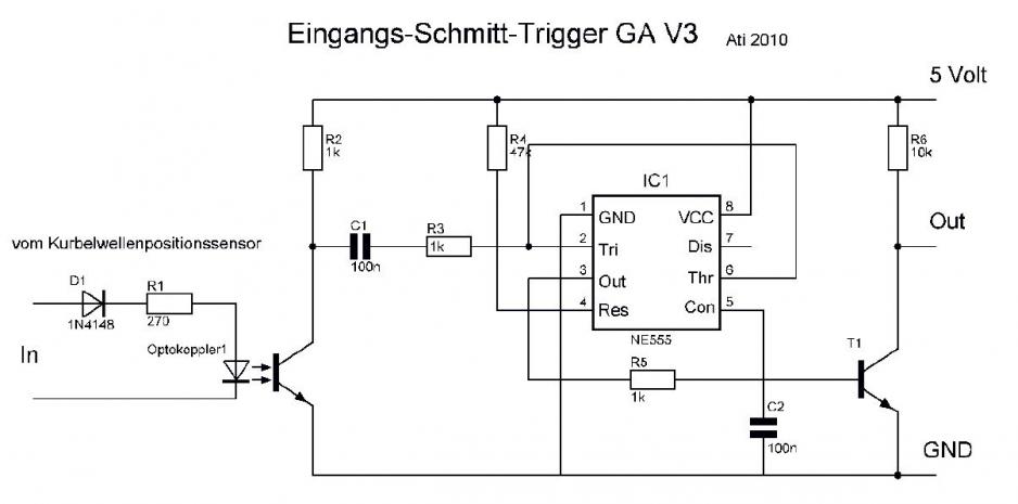
plan impulse treatment
for gear indicator V3
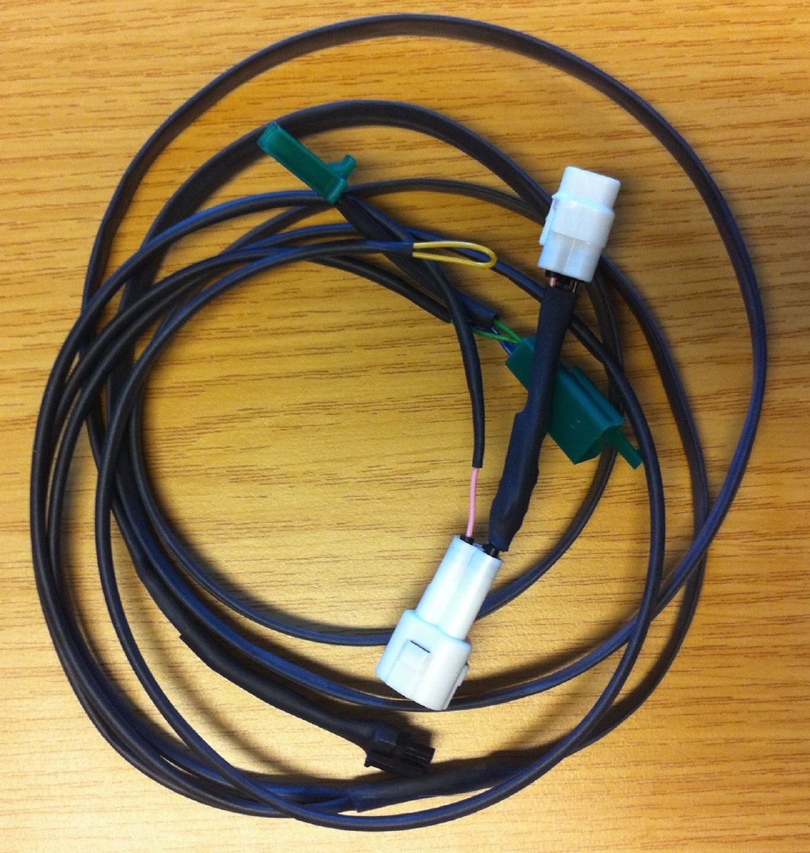
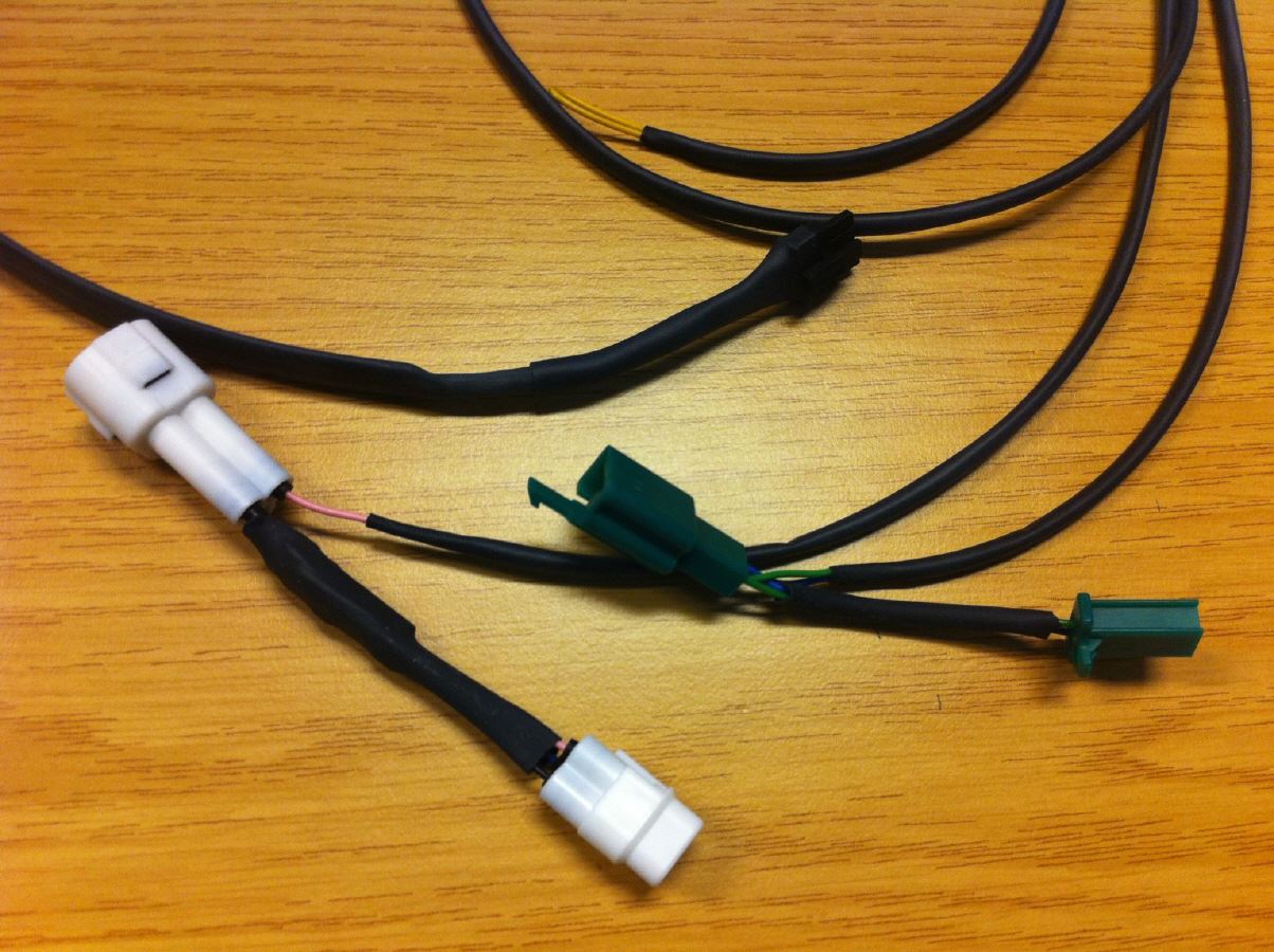
To make the installation of the gear display optimally , a harness has emerged.
This harness goes from the GA V3 in the speedometer to the actuators and sensors in the bike.
Strictly speaking there are four wires , which are summarized in a harness . The colors of the wires are as far as possible the Suzuki scheme adapted . The pink wire goes to the gear sensor adapter. This adapter allows for decoupling of the gear sensor from the ECU . Linked to this , there is also the function of the so-called G- packs. With this particular circuit , both the idle display and the side stand switch will continue to function . For the SV is set as the transition of the fourth gear. This ensures that no throttling by the ECU to enter into force .
The green and the blue wire going to the crankshaft position sensor connector. Green wire to green wire and blue wire to green / blue wire.
The yellow wire goes to the optional light overload relay. It controls the on-/off-switching the pig launcher.
The wires are automotive cables with a cross section of 0.35 mm, which does not make them a hand so thick , and on the other hand is more than enough . All together are housed in a shrink tube and thus optimally protected against chafing and other damage. And it looks decent as well.
For the GA V3 a two-pole and four-pole N-Lock Micro connector is required depending on the speedometer . The four-pole , the wire harness is connected. The bipolar used to lead out of the switch flash.
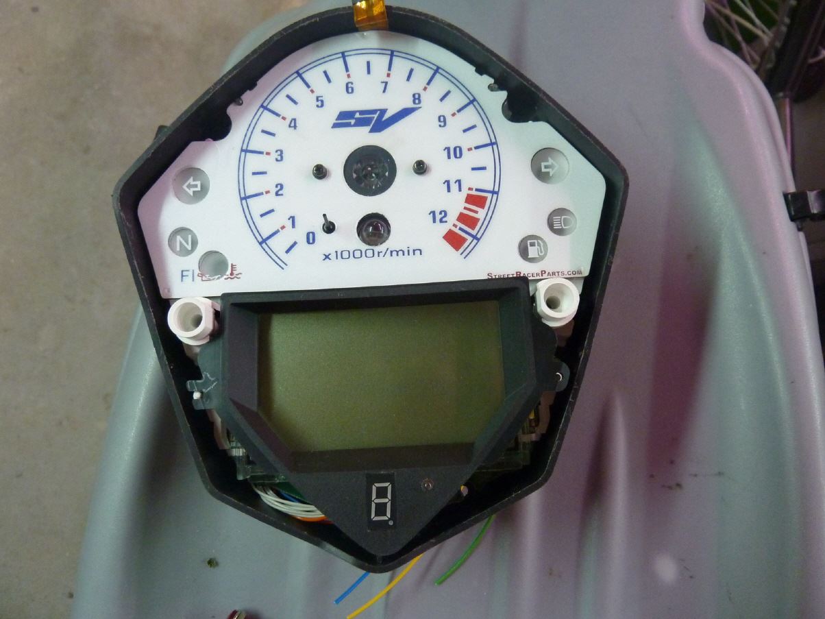
 Ganganzeige V3
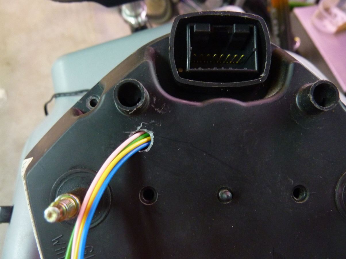
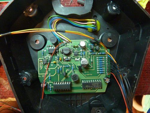
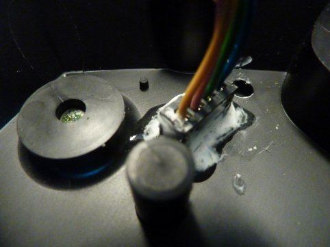
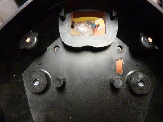
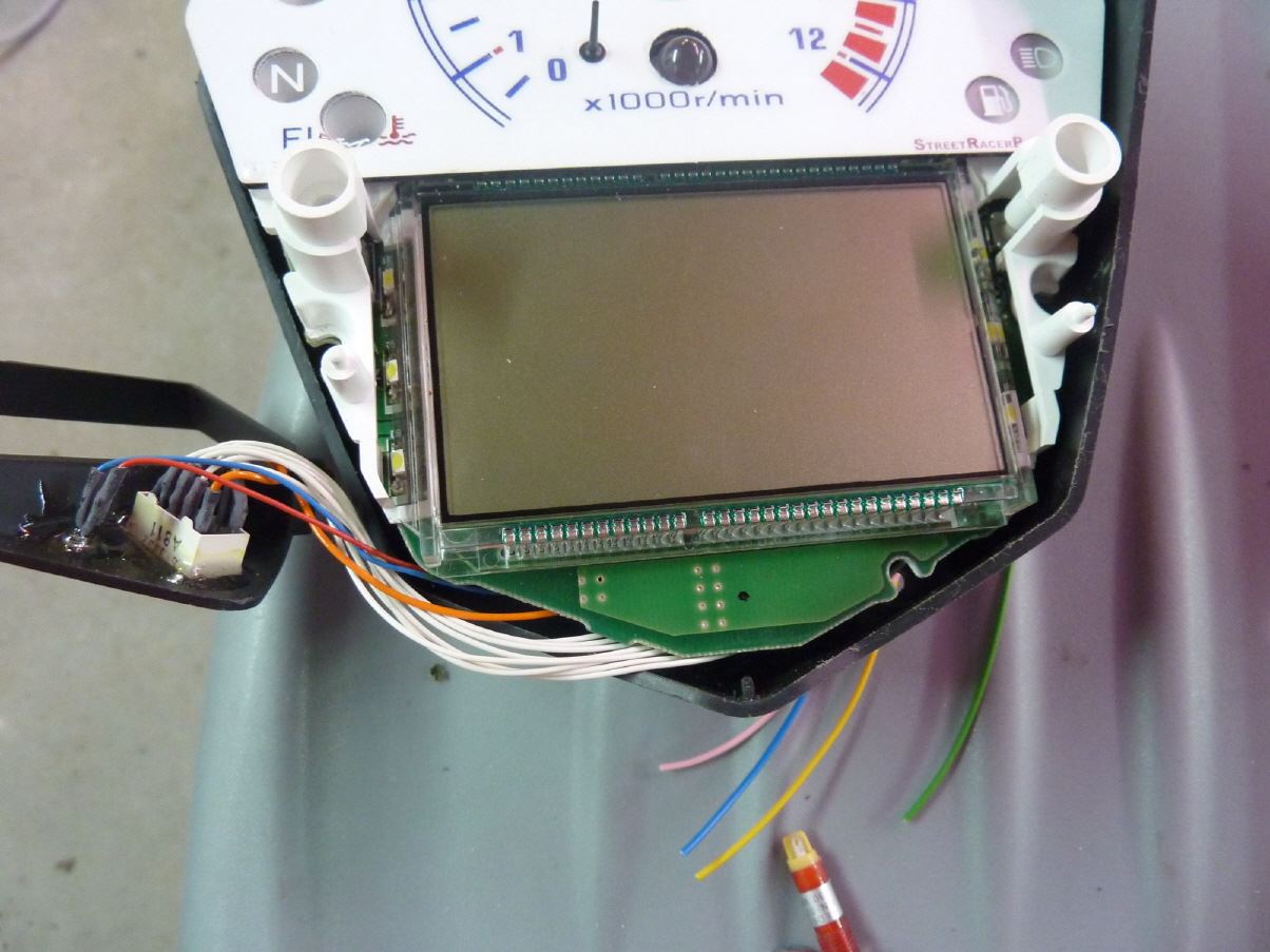
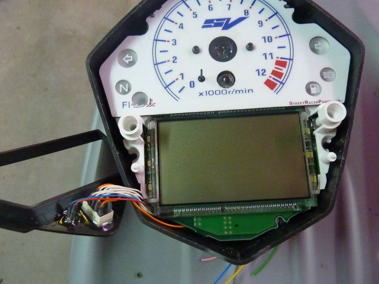
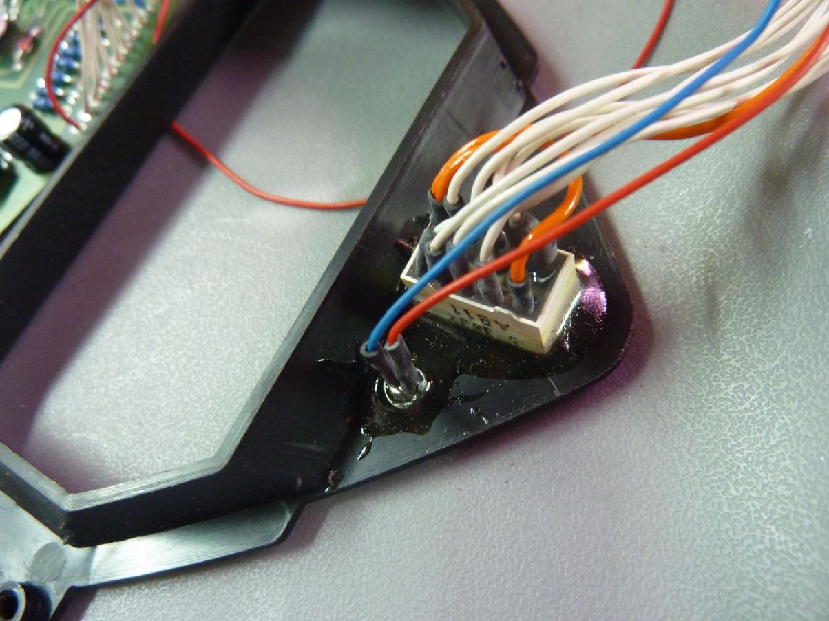
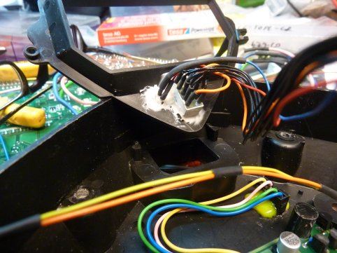
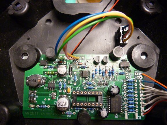
In the pictures you can now see how the GA-V3 (here the prototype yet) is installed. The circuit board is adhered by means of adhesive pads on the base shell. The pictures show how misplaced the connecting wires of the digit clean.
Furthermore, the crankshaft position sensor connector is visible. He sits behind the left side cover. There the appropriate plug adapter is installed. The right gear sensor counterpart is inserted between the gear sensor connector. For the "high-end" version (ie with light control), there is the yellow wire that controls the light overload relay. The installation is actually already finished.
The speedometer itself is now a four-pole N-Lock Micro connectors, which makes contact to the cable harness. In order outside the tachometer everything is just stuck.
At the two-pole N-Lock Micro Connectors an external power LED is connected. Logically, one places the LED above the speedometer / tachometer.
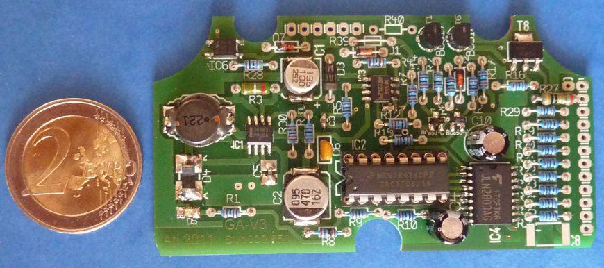
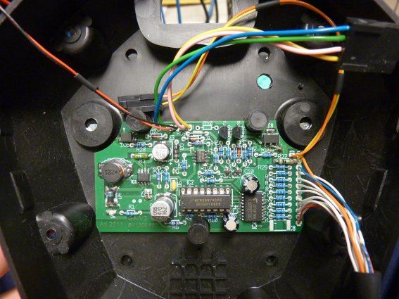
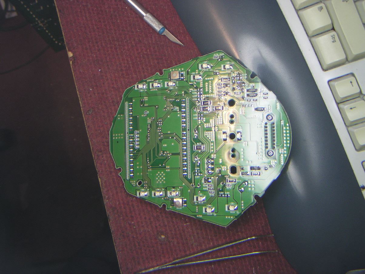
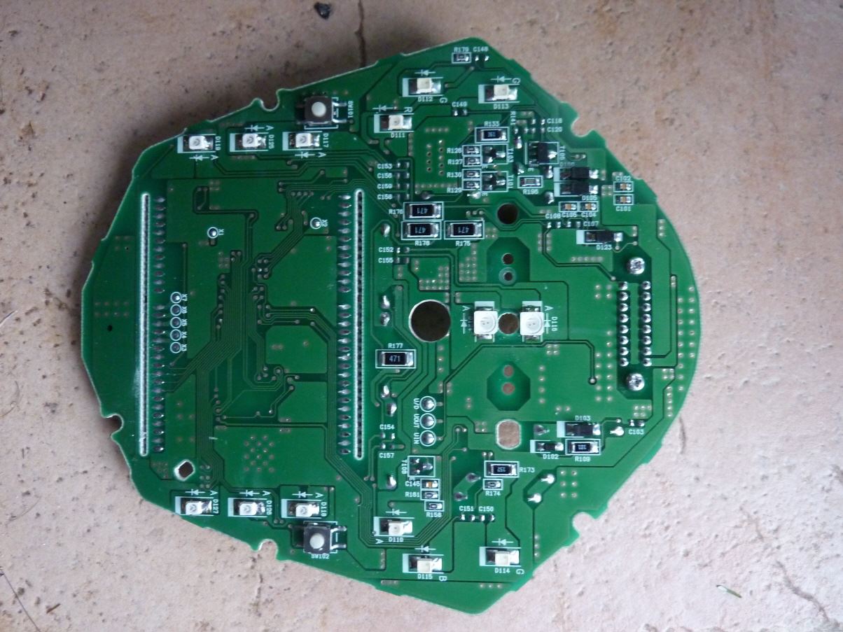
Board compared to a coin
ready assembled board V3
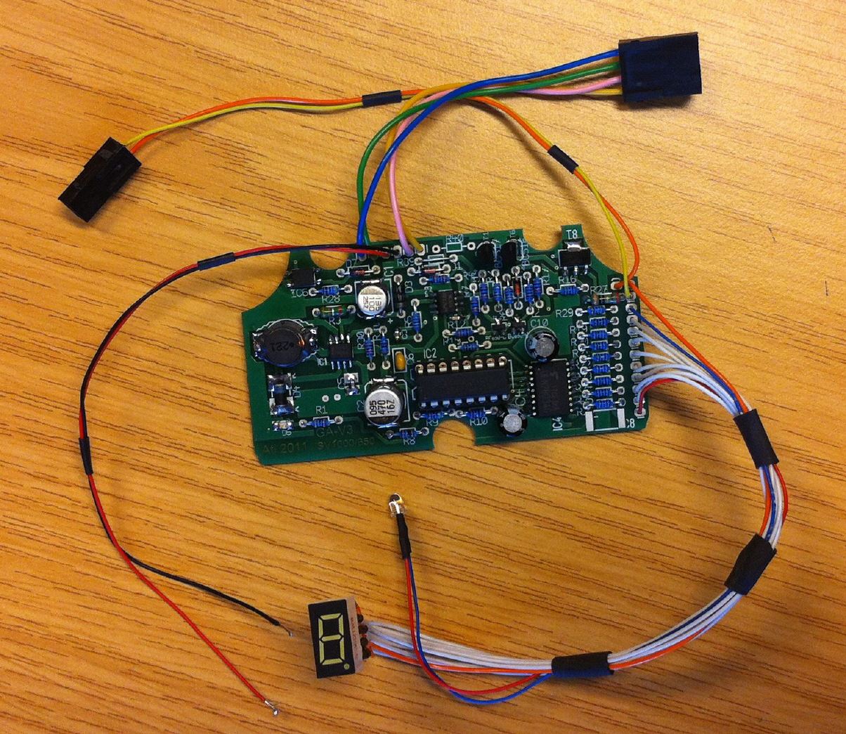
below now the whole installation kit . In the figure the circuit board with microprocessor is completely wired to see . This board is built into the speedometer. In detail - the board below the main board in the housing of the speedometer . The number and the brightness sensor to be installed in the black plastic triangle
below the display. The one or two connectors are glued into the lower half-shell of the speedometer . The speedometer can be staked by the latching connectors so easy when it must be time .
The harness is made up all ready . Both the gear sensor adapter , and the crankshaft sensor signal adapters are plug & play performed. The control wire is already drawn into the optional lighting control. Because of this and the harness of the SV has to be slightly modified , the whole is optional. The lighting control system replaces the non-existent light switch by turning it off the headlights with the engine off . Only when the engine reaches a minimum speed should be switched the headlight. This increases the starting potential of the battery and prevents rapid discharge of the battery at a standstill